Design steps of hot runner plastic mold
First of all, according to the structure and use requirements of the plastic parts, determine the position of the feeding port. As long as the structure of the plastic part allows, the nozzle and nozzle head in the fixed mold insert will not interfere with the molding structure, and the inlet of the hot runner system can be placed at any position of the plastic part. The position of the feeding port of traditional plastic injection molding is usually selected according to experience. For large and complex special-shaped plastic parts, computer aided analysis (CAE) can be used to simulate the flow of molten plastic in the cavity, analyze the cooling effect of each part of the mold, and determine the ideal entrance position.
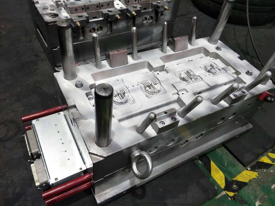
plastic mold
Secondly, the spray head form of hot runner system is determined. The material and product use characteristics of plastic parts are the key factors to select the type of nozzle. The production batch of plastic parts and the manufacturing cost of molds are also important factors to select the type of nozzle.
Third, determine the number of cavities for each mold according to the production batch of plastic parts and the tonnage of injection equipment.
Fourth, the number of nozzles is determined by the location of the feed port and the number of cavities in each mold. If a product is formed, select a mold, a workpiece and a feeding port, and only one nozzle is required, that is, select a single head hot runner system; If a product is formed, if more than two inlets are selected in one mold or one mold, multiple nozzles are required, that is, in addition to the mold structure with cross runners, a multi head hot runner system is selected.
Fifthly, determine the radial size of the nozzle according to the weight of the plastic parts and the number of nozzles. At present, nozzles of the same shape have several size series to meet the molding requirements of plastic parts in different weight ranges.
Sixthly, according to the structure of the plastic parts, determine the size of the mold structure, select the standard length series size of the nozzle according to the thickness of the fixed insert and the fixed template, and finally trim the thickness size of the fixed template and other dimensions related to the hot runner system.
Seventh, determine the shape of the hot runner fixing plate according to the shape of the hot runner plate, arrange the power lead slot on the plate, and design sufficient cooling water circuit near the hot runner plate, nozzle and nozzle head.
Eighth, complete the plastic mold design drawings of the hot runner system.


