Sharing experience in injection mold design
Before design
1. Check the product structure (draft, wall thickness, undercut, mold direction, parting surface direction, gate position)
2. Tonnage, model and type of injection molding machine, inlet diameter of mold gate bushing and diameter of locating ring are used.
3. The size of the ejector pin and the position of the ejector hole, the depth of the injection molding machine into the mold, the size of the mold base, and the closing height.
4. Electric injection molding machine and hydraulic injection molding machine are completely different in mold design.
5. Generally speaking, pressing plate coding die, screw coding die, hydraulic coding die, magnetic coding die, etc. are commonly used in the coding mode of injection molding machine.
6. Product problem points, thread clamping, materials and shrinkage.
7. The plastic shrinkage must be confirmed with the customer to understand the brand of the final material they produce.
8. What additives need to be added.
9. If there are embedded hardware or other objects, they should also be considered.
10. It is better to be familiar with the assembly relationship of the product and the use of the product. This information is helpful for the mold meter.
11. What are appearance surfaces, what are non appearance surfaces, where the draft angle can be increased at will, and what cannot be changed.
12. Even the buckle structure can be cancelled or changed into another simple form.
13. Mold design is the process of simplifying complex problems.
14. The downstream process shall be fully considered.
15. External parameters of mold water circuit, oil circuit, circuit and gas circuit.
Like the design sequence of four circuits: oil circuit, water circuit, gas circuit and circuit.
The placement order on the mold is that the circuit, water circuit, air circuit and oil circuit are closest to the TOP direction.
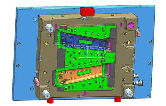
In design – parting
1. The simpler the parting surface is, the better. Those that can be stretched out must not be scanned.
2. When pulling the parting surface, take a holistic view, simplify the parting surface as much as possible, and avoid those 0.1~0.5 penetration positions that can be avoided.
3. The parting surface should also follow the principle of following the product trend as far as possible.
4. If the angle of penetration surface is large, the area of penetration surface is large.
5. The pillow seat can be pulled out as wide as possible.
6. After the parting surface pulled by hand is made into the actual mold, the master in charge of flying mold will not scold you.
7. When making the parting surface, you must consider the arrangement of the sliding block and the inclined roof, because those also involve the change of the parting surface.
8. The typical slider structure is a trigonometric function relationship. It is necessary to ensure that the angle of the inclined guide post is not too large, and try to be below 30 degrees.
9. The principle for the selection of inclined guide pillar is to be as rough as possible. Don’t be too stingy, because the inclined guide pillar is forced.
10. The sliding block is divided into many variable structures, such as uphill, downhill, inward pumping, oil cylinder pumping, front mold sliding block, sliding block with sliding block, sliding block with reverse jacking,
Slider with inclined roof, etc,
11. The purpose of making full use of the trigonometric function is to realize the stripping of the product undercut and the normal opening and closing of the mold.
12. The inclined roof is relatively flexible, and the angle of typical inclined roof shall not exceed 15 degrees as far as possible. Refer to trigonometric function and theoretical mechanics for specific principles.
13. The shape of the inclined roof has many evolutionary forms, such as the inclined roof on the uphill, the inclined roof on the downhill, the inclined roof at the neck, and the large inclined roof with the inlaid inclined roof rods
Top, large inclined roof of inlaid round bar, small inclined roof of inlaid hanging platform, inclined roof under the top block, inclined roof on the sliding block, inclined roof on the sliding block
Those with inclined roof and those with reverse roof on the inclined roof have the same purpose and use trigonometric functions to make the product undercut.
14. After the design is completed, the relationship between lower trigonometric functions must be verified,
15. Simulate the opening and closing of the mold, and consider whether there will be problems during injection molding.
In design – alignment
1. Two plate mold, three plate mold, hot runner, IMD, IML, two-color, stacked mold, etc.
2. Die structure types are all designed to achieve mass production of products.
3. After the mold base is selected, the principle of inlaying is to simplify processing.
4. Save materials and facilitate product molding, such as exhaust, etc.
5. In your opinion, there are very thin parts on the mold, which must be spliced separately for easy replacement in the future.
6. The strength and processability of inserts and the designability of future waterways shall be fully considered when inlaying.
7. After inlaying, standard parts will be added.
8. The principle of adding standard parts is to focus on key points first and then place them locally, and try to arrange them in a balanced and symmetrical way.
9. First add the ejector pin. When adding the ejector pin, the layout of the waterway must be considered.
10. Give priority to the arrangement of the ejector pin, and then design the waterway, and then adjust the waterway ejector pin according to the actual situation to balance the two.
11. The principle of ejecting is to place the product where the gripping force is large, and to place the product where the strength structure is good, such as the edge, platform, and edge,
To avoid white top or uneven top out.
12. The principle of drainage road is to add the principle of ejecting. Where the product holds tightly, it is also the hot spot of the product, and cooling should be strengthened
This contradiction needs to be well adjusted.
13. As for whether to use the ejector rod or the ejector block or the push plate, specific problems need to be specifically analyzed.
This should be analyzed in combination with the structural characteristics of the product. For example, if the product is easy to stick to the front mold, we should consider whether to add an undercut to the back mold,
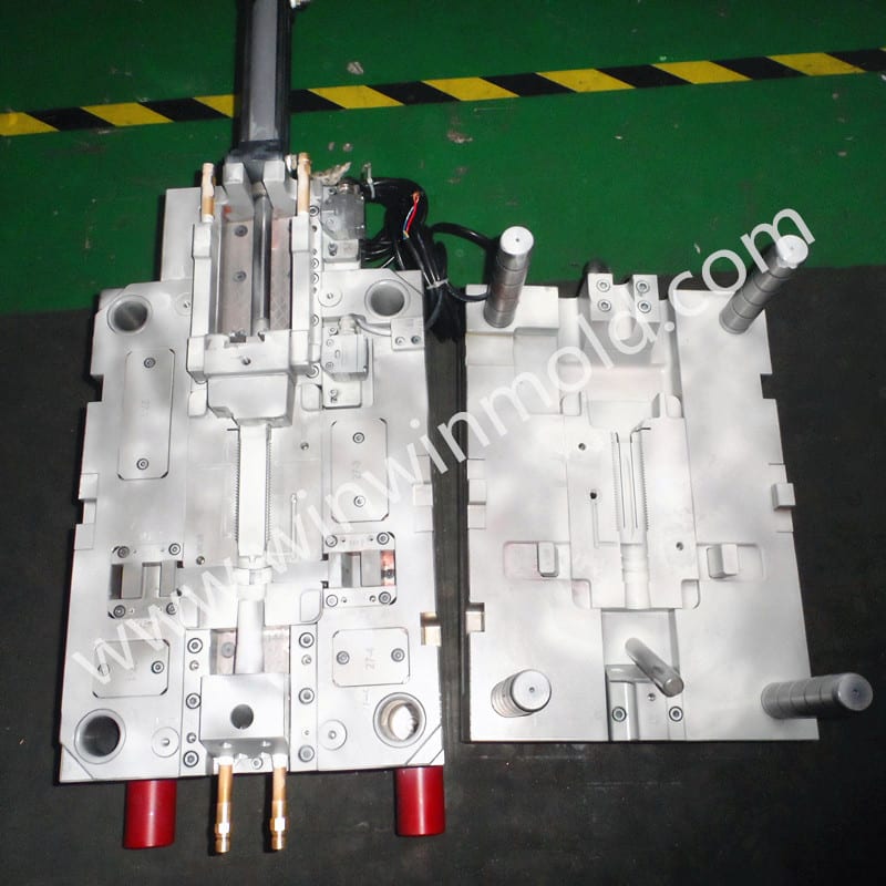
Or front die plus ejection.
14. After the top bar waterway is added, the remaining standard parts shall be balanced symmetrically as far as possible.
After design – check
1. After the completion of the whole set of mold design, the first step is the draft analysis of the insert to see if there is any undercut.
2. Secondly, it is the most important to check the interference of all parts of the mold.
3. Then it is the simulation of mold opening and closing. As long as the mold is not too clear, it must be simulated.
4. Machinability of each part of the mold and assembly process of the mold.
